
Contact
Baltic Windtunnel GmbH
Gewerbegebiet 4
18276 Lüssow OT Karow
Germany
Fon: +49(0)3843/6998930
Fax: +49(0)3843/855556
Web: www.windtunnel24.com
Mail: info@windtunnel24.com
Windtunnel WT397
[yith_currency_shortcode slug="list-select"]
Price without mounting on customer site and without transport
Measuring cross section: 1200 x 1200 mm
Max. windspeed: 50 m/s
Technical Description WT397
1. General Description
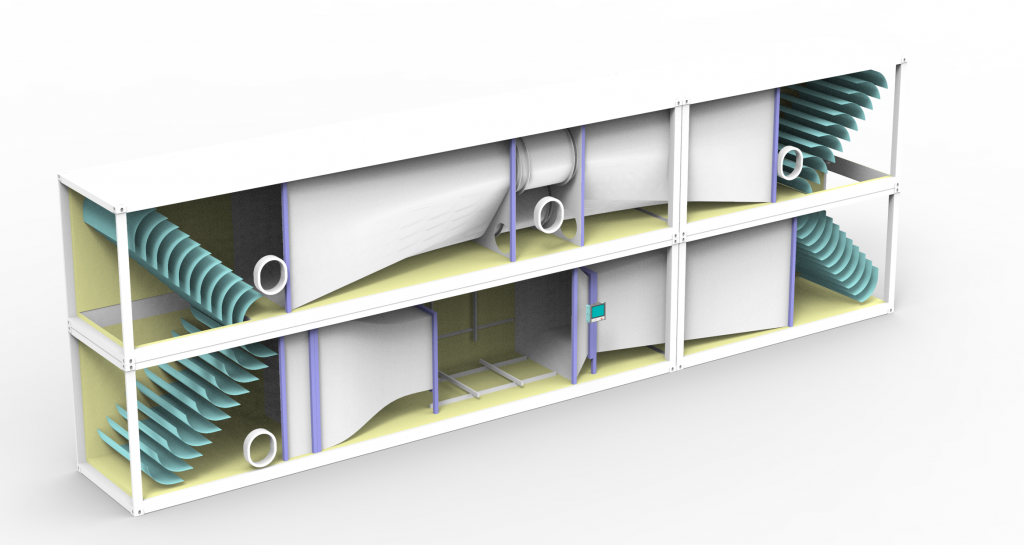
The WT397 is a Closed Loop wind tunnel specifically designed for installation and direct operation within containers. The complete facility must be accommodated across two stories within a 40 ft and a 20 ft High-Cube (HC) container.
The maximum installation area must not exceed 18.5 by 5 m. The containers must be of first quality, and the exterior must be painted white. The design must guarantee sealing for air tightness and protection against bad weather. Manholes must be provided for maintenance work. Thermal insulation inside the container is requested as a baseline offer.
Technical Data
| Design Type | closed loop | |
| Measuring cross section | mm | 1500 x 1500 |
| Measuring length | mm | 3000 |
| Max. windspeed | m/s | – |
| Turbulence | % | <2% |
| Contraction | 2.33 |
2. Basic Structure and Test Section
The WT397 is a closed loop system installed within the container structure.
The Test Section: It must have a minimum cross-section of 1500 x 1500 mm and a length of 3000 mm. It should preferably be designed as an open test section. The entire surface of the test area must be painted matt black. A lighting system is required, with an intensity of greater than or equal to 500 Lux.
Mounting and Access: A mounting system must be present on the floor and the opposite wall, allowing for full-surface modular fixation, for example, using 40 x 80 aluminum profiles with a 10 mm gap. A window at the control station must provide sight of the entire test area. A door leading from the control station to the test area must be provided, measuring a minimum of 1 x 2.15 m. Doors and optional windows must withstand pressure. The entrance door to the control station must be lockable. A window facing outside in the control station (minimum 800 x 600) is preferably required and must be able to be darkened.
Optional Equipment: Optionally, a lockable pit for the installation of a Hexapod can be integrated. The use of the entire cross-section without a nozzle is also optionally possible, although the flow quality requirements do not apply in this mode.
3. Flow Conditioning and Quality
The flow conditioning components, specifically screens and honeycombs, must be designed to be easily removable and cleanable in less than 2 hours. Access to all areas for maintenance and cleaning must be guaranteed.
Flow Quality Verification: The Turbulence Intensity and Uniformity must not exceed 3 % (target value: less than or equal to 2 %). The Orthogonal Velocity must be less than 1 % of the test velocity. Uniformity must be measured in a 1 x 1 m zone in 3 sections (Inlet, Middle, Outlet). Turbulence intensity must be measured using a CTA Hot-wire in the Center, and the calibration must be proven via a Prandtl probe.
4. Control, Regulation and Sensor System
The control station must be set up as a workshop. It requires a minimum of 10 sockets (220 V) and at least 2 RJ45 network sockets on the floor. The control system should be positioned near the window. One controller for all motors is required. The power electronics must be housed in a control cabinet in the control station and designed for 400 V and 50 Hz.
The display must show the current speed and the rotational speed (accurate to 1 RPM). An emergency stop switch must be present. A cable duct for sensors from the control station to the test area and an interface for power and network connection on the control stand are required. A retractable probe for center speed measurement in the test area is foreseen.
5. Control, Regulation, and Software
The control unit continuously visualizes all relevant operating data, including wind speed, temperature, barometric pressure, humidity, Reynolds number, and turbulence intensity.
The integrated sensor system for speed control and measurement includes a barometric pressure sensor, a temperature sensor, and two differential pressure sensors for the Pitot tube, to precisely cover the entire velocity range. The determination of the wind speed is achieved with an accuracy of ±1% of the measured value in the relevant velocity range of 10 m/s to 50 m/s. For monitoring flow homogeneity, six symmetrically distributed Prandtl tubes are additionally installed at the nozzle exit.
The included software supports the simultaneous data logging of all system parameters. This includes wind tunnel data (speed, temperature, barometric pressure, humidity), traverse positions, pressure scanner values, and data from the 6-axis balance, allowing for a complete system state capture. Furthermore, the software is capable of executing fully automated measurement campaigns. This involves programming speed ramps, setting the traverse positions accordingly, individual measurement of the pressure channels, and defining the logging times.
6. Additional Requirements and Options
Operation and Maintenance: The temperature fluctuation must remain under 5°C over a minimum of 3 hours of operation; otherwise, climate control is required. Maintenance access to the fans must be guaranteed on the roof of the control station. The insulation of the control station and the wind tunnel is a scoring criterion.
Warranty and Documentation: A minimum of 5 years warranty plus software updates is required. The provider must provide information on the estimated lifespan and availability. Proof of compliance with environmental aspects and details regarding carbon footprint from transport must be submitted. Offers are scored 60 % on specifications met, 30 % on the lowest price, and 10 % on environmental aspects met.
Optional 6-Axis Balance: Optionally, a 6-axis balance with 3 forces and 3 moments can be included. The capacities are 1 kN for forces and 200 Nm for moments. The measurement accuracy must be less than or equal to 1 %. Calibration at 10 points plus matrix and a 2-year warranty are required for the balance. The balance fixation can be on the wall or the floor of the test area.
Accesories
⚠️ Note: Any power electronics or control units shown in images are not included in the base price and must be purchased separately.