
Contact
Baltic Windtunnel GmbH
Gewerbegebiet 4
18276 Lüssow OT Karow
Germany
Fon: +49(0)3843/6998930
Fax: +49(0)3843/855556
Web: www.windtunnel24.com
Mail: info@windtunnel24.com
Windtunnel WT440
[yith_currency_shortcode slug="list-select"]
Price without mounting on customer site and without transport
Measuring cross section: 2500 x 2500 mm
Technical Description WT440
1. General Description
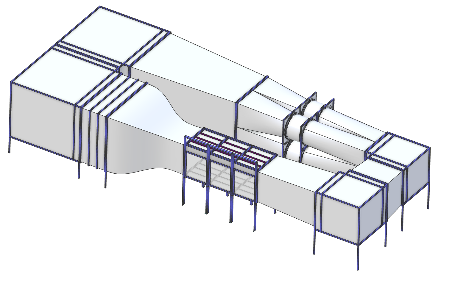
The WT440 wind tunnel is designed as a closed-circuit return-loop system with a fully enclosed test section. This design ensures precise flow guidance, high energy efficiency, and excellent long-term operational stability. The system is engineered for demanding aerodynamic applications and achieves a maximum adjustable flow velocity of up to 50 m/s, with fully variable speed control.
Thanks to its modular segmentation, the WT440 can be installed even under strict logistical constraints, despite being a large-scale aerodynamic facility. Based on the official ground plan, the true external dimensions of the WT440 are:
• Total length: 28.35 m
• Total width: 11.73 m
• Total height: 5.98 m
These dimensions result from the full return-loop ducting with two parallel legs, the vertical height of the loop, and the structural components around the fan and diffuser sections.
The WT440 also fulfills the requirement for precise control in the low-speed regime. The integrated Low-Speed Option enables stable flow velocities between 1 m/s and 4 m/s, supported by tachometer sensors on all four fans. This allows the WT440 to support both high-speed aerodynamic testing and sensitive low-speed investigations.
Technical Data
| Design Type | closed loop | |
| Measuring cross section | mm | 2500 x 2500 |
| Measuring length | mm | 6000 |
| Max. windspeed | m/s | |
| Turbulence | % | 0,75% |
| Contraction | 3,74 |
2. Basic Structure
The WT440 features a modular, bolted structural design. All main segments are constructed as functional modules that can be transported, installed, and serviced individually. This modularity simplifies logistics and ensures excellent maintainability.
The closed-circuit loop consists of:
• Settling Chamber equipped with honeycombs and stainless-steel screens
• Nozzle with a contraction ratio of 3.74
• Test Section with a cross-section of 2500 × 2500 mm and a length of 6000 mm
• Multi-stage diffuser system for controlled flow deceleration
• Fan Unit housing four axial high-performance fans
• Return-duct system including multiple corners, diffusers, and transition elements
The fully glazed test section provides unrestricted optical access, ideal for PIV, laser-sheet techniques, and flow visualization. Numerous access panels allow maintenance of internal components such as honeycombs and screens.
3. Flow Conditioning and Turbulence Level
The WT440 is optimized for extremely low turbulence intensity. At the nozzle exit, the wind tunnel achieves a turbulence level of 0.75 percent, measured across 75 percent of the cross-sectional area at 50 percent of maximum wind speed.
The settling chamber includes:
• Honeycombs for swirl removal and cross-flow suppression
• At least three continuous stainless-steel screens without obstructing frames
• Aerodynamically optimized transitions for minimal boundary-layer growth
The nozzle accelerates the flow smoothly and transfers it into the test section with minimal loss. The downstream diffuser returns the flow efficiently and contributes significantly to the energy recovery of the loop.
An optional turbulence monitoring system can be integrated, providing continuous, real-time flow-quality assessment.
4. Drive Concept
The WT440 drive system is based on four axial high-performance fans, operating in parallel within a shared fan module. This configuration provides:
• high volumetric flow rates
• uniform pressure distribution
• stable operating conditions
• redundancy and smooth performance in long-term operation
All fans are vibration-isolated to prevent mechanical resonance and measurement disturbances. Speed control is achieved via frequency-controlled power electronics, allowing synchronized and stepless adjustment of all four fan speeds.
Line filters and inductive chokes ensure minimal electrical feedback into the supply grid and protect sensitive measurement equipment. Operation can be performed via a local touch display or remotely through software.
The Low-Speed Option provides precise control down to 1 m/s, enabled by tachometer sensors on each fan. Alternatively, the WT440 can be operated without the central control unit using a simple 0–10 V interface from the power electronics — ideal for external integration or simplified test setups.
5. Control, Regulation, and Software
The control system visualizes all critical operating parameters in real time:
• Flow velocity
• Temperature
• Barometric pressure
• Humidity
• Reynolds number
• Turbulence intensity
The sensor suite includes:
• barometric pressure sensor
• temperature sensor
• two differential pressure sensors for Pitot tube operation
• six symmetrically positioned Prandtl tubes at the nozzle exit for flow-uniformity monitoring
Velocity measurement accuracy is ±1 percent within the range of 10–50 m/s.
The software offers:
• simultaneous data logging of all system parameters
• control of 2D and 3D traverse systems
• integration of an external pressure scanner
• full support for a 6-component balance
• fully automated measurement campaigns including ramps, motion profiles, and defined logging intervals
6. Integrated Measurement Equipment and Details
The WT440 can be equipped with extensive aerodynamic measurement systems:
• 6-component aerodynamic balance
• 24-channel pressure scanner with selectable pressure ranges
• external 3D traverse system (typically 1200 × 1200 × 900 mm)
• internal 2D traverse system with high repeatability (±0.5 mm)
• professional fog generator for visualization at full flow speed
All components are designed for high-precision aerodynamic measurements and support both industrial applications and advanced research activities.
⚠️ Note: Any power electronics or control units shown in images are not included in the base price and must be purchased separately.