
Loading...
-
WT237
Ammonit Wind Tunnel - Germany
-
WT278
Uni Eindhoven - Netherlands
-
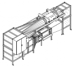
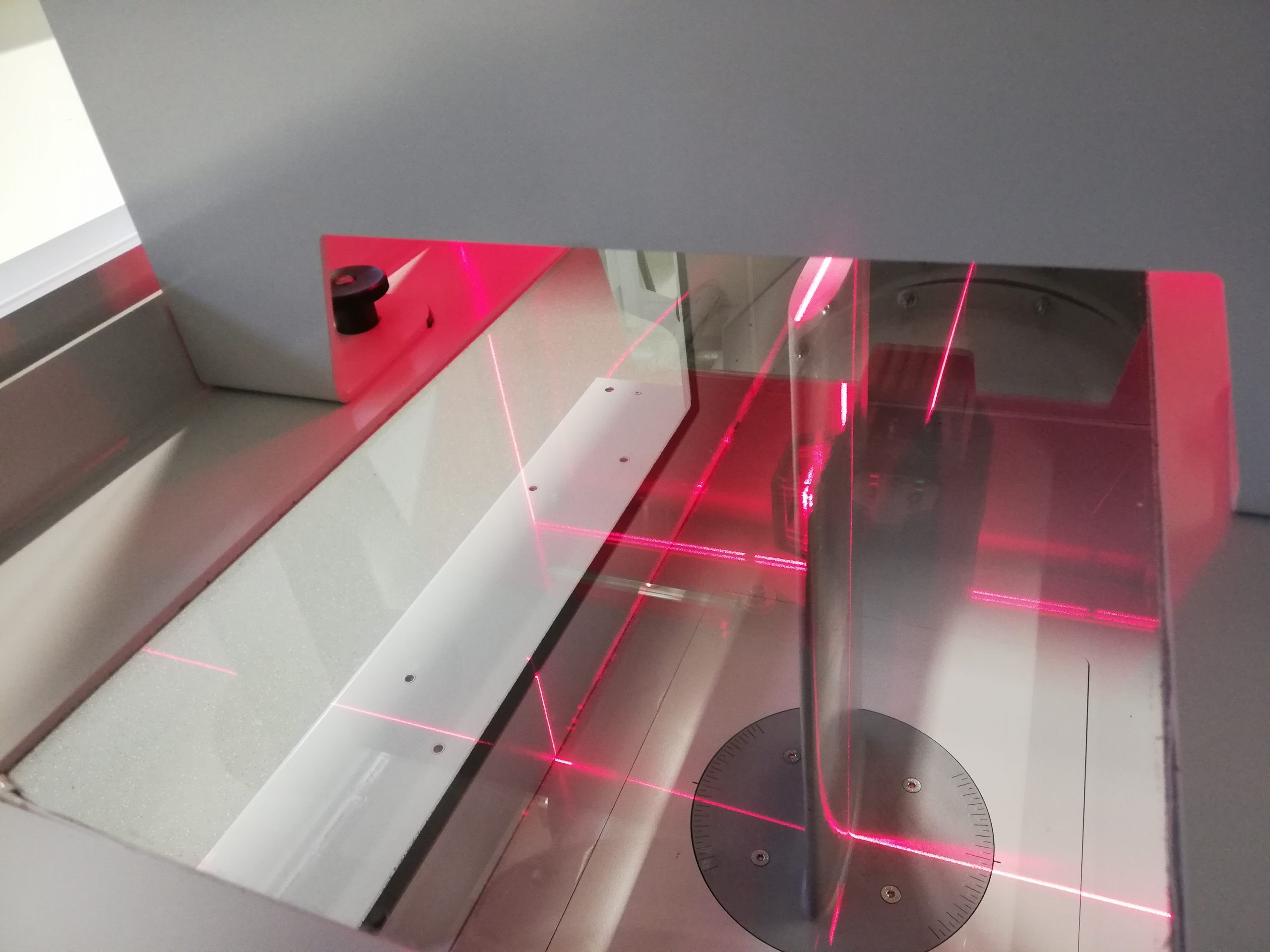
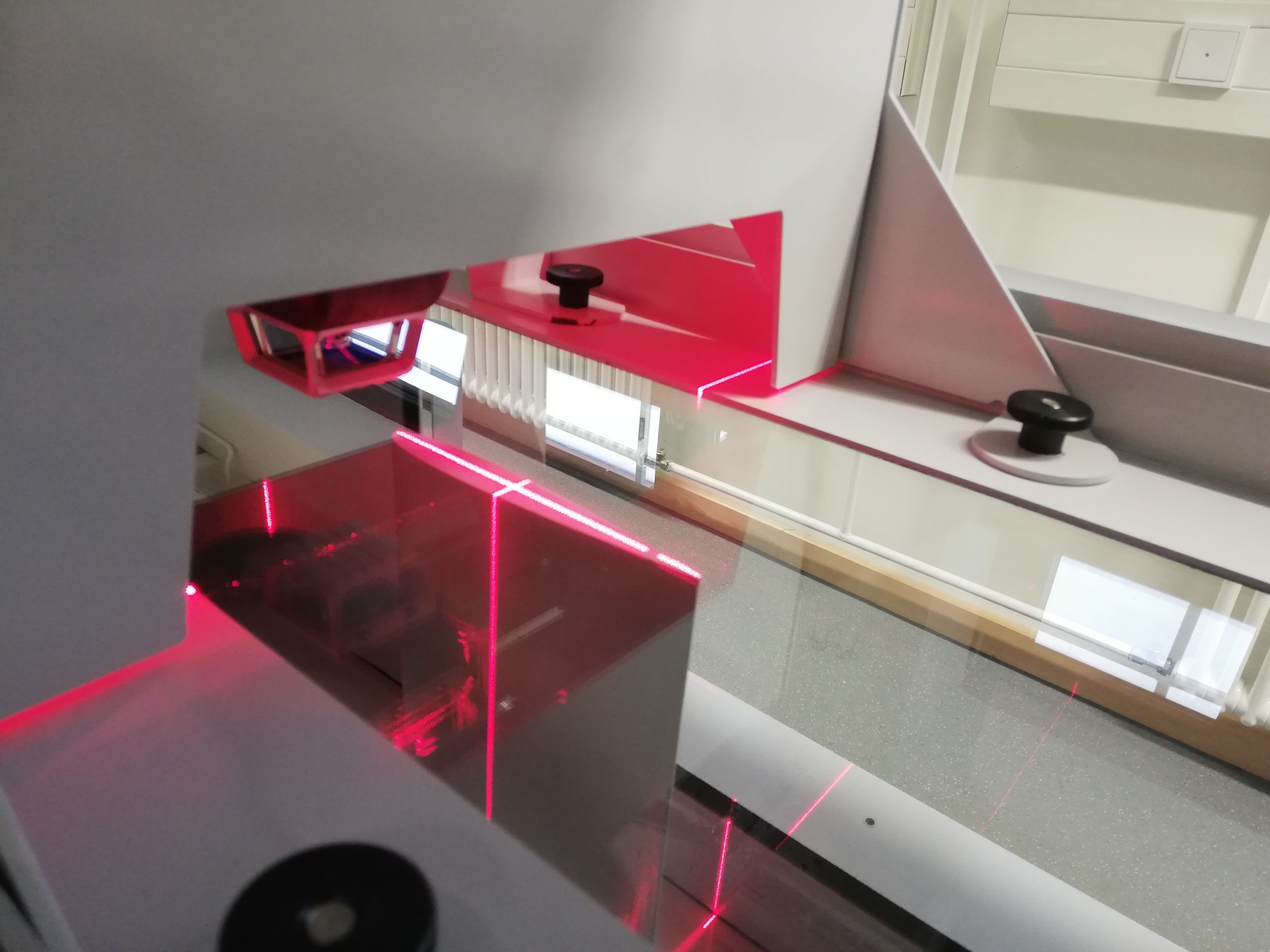
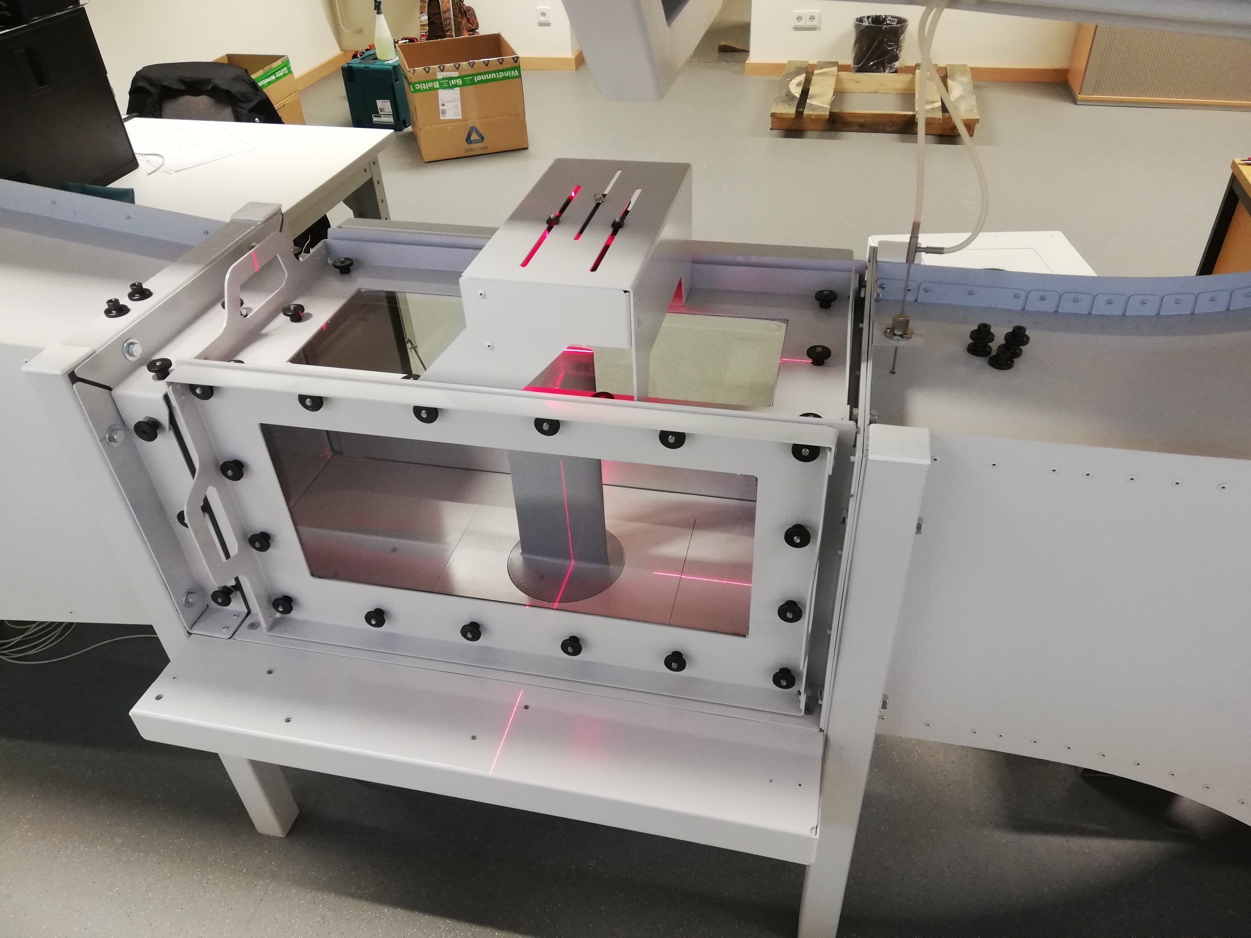
WT307
TH Köln - Germany
-
WT344
Uni Bundeswehr München - Germany
-
WT341
Airbus Warsaw - Poland
-
WT278
Uni Eindhoven - Netherlands
-
WT278
Uni Eindhoven - Netherlands
-
WT342
INTA Madrid - Spain
-
WT342
Uni Wollogong - Australia


Copyright © 2023. Baltic Windtunnel GmbH. All Rights Reserved. Powered by Adssential.