
Contact
Baltic Windtunnel GmbH
Gewerbegebiet 4
18276 Lüssow OT Karow
Germany
Fon: +49(0)3843/6998930
Fax: +49(0)3843/855556
Web: www.windtunnel24.com
Mail: info@windtunnel24.com
Windtunnel WT389
[yith_currency_shortcode slug="list-select"]
Price without mounting on customer site and without transport
Measuring cross section: 1200 x 1200 mm
Max. windspeed: 50 m/s
Technical Description WT389
1. General Description
The WT389 wind tunnel is designed as a Closed-Circuit (Return Loop) with an enclosed test section. This design enables controlled flow guidance and high efficiency. The system is built for high performance and achieves a maximum adjustable flow velocity of up to 50 m/s. The wind speed is continuously adjustable.
The design takes strict logistical requirements into account. Installation must take place in a confined space measuring a maximum of 13 m in length, 3 m in width, and 5 m in height. Delivery is possible via a lift measuring 2 m × 2 m × 5 m with a maximum load capacity of 2000 kg. The WT389 also fulfills the requirement for precise controllability in the low-speed range (Low Speed Option), allowing velocities between 1 m/s and 4 m/s to be achieved.
Technical Data
| Design Type | closed loop | |
| Measuring cross section | mm | 1200 x 1200 |
| Measuring length | mm | 1650 |
| Max. windspeed | m/s | 50 |
| Turbulence | % | 0.6 at 50 m/s |
| Contraction | 2.78 |
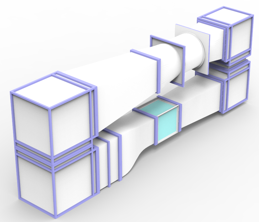
2. Basic Structure
The WT389 has a modular structure to simplify transport, installation, and maintenance. All main components are constructed to be bolted together and can be disassembled if required. This structure allows individual segments to be handled as functional modules.
The basic structure of the closed circuit includes the following essential modules:
• Settling Chamber: Contains the honeycomb flow straighteners and screens for flow smoothing.
• Nozzle: Used for flow acceleration. The contraction ratio is 2.78.
• Test Section: With dimensions of 1200 mm × 1200 mm in cross-section and a length of 1650 mm.
• Diffuser: Used for flow deceleration.
• Fan Unit: Contains the axial fan, which is ideally mounted with vibration isolation.
• Return Loop: Connects the diffuser and the settling chamber to close the circuit.
The test section of the WT389 is equipped with large transparent side windows, which occupy the full height of 1200 mm (from floor to ceiling), enabling visual monitoring and the use of optical measurement techniques.
Regarding maintenance, the wind tunnel is designed so that all internal parts are accessible for cleaning. This is achieved via access flaps, which notably allow access for cleaning between the screens and to the honeycombs, without requiring complete disassembly.
3. Flow Conditioning and Turbulence Level
The flow conditioning in the WT389 is designed for the lowest possible turbulence intensity. The system is optimized so that the turbulence intensity at the maximum velocity of 50 m/s is less than 0.6%, measured over 50% of the cross-section.
The settling chamber contains Honeycombs (Wabengleichrichter), which align swirl and cross-flows. These fulfill the strict requirements for the length-to-diameter ratio, which is 8.4 (80 mm length and 9.5 mm free diameter).
This is followed by a minimum of three screens made of stretched stainless-steel wire mesh, which contribute to further flow smoothing. To prevent flow disturbances caused by stabilizing frames, each screen is executed as a single continuous piece, without physical obstacles disturbing the free cross-section. The screen tension is typically between 30 N/cm and 40 N/cm, exceeding the minimum requirement of 20 N/cm.
Subsequently, the air passes through an aerodynamically shaped nozzle, which accelerates the flow. The transitions between the modules are optimally designed—especially between the straightener, nozzle, and diffuser—to ensure thin boundary layers and prevent flow separation. A crucial component of flow quality is the fan unit, whose blade configuration and setting are individually adapted to the planned operating conditions.
The wind tunnel utilizes a contraction ratio of 2.78. This value exceeds the required specification of 2.5 and serves to ensure flow quality and effectively reduce the turbulence intensity.
Optionally, the WT389 can be equipped with an integrated turbulence measurement system. It is directly connected to the control unit and enables continuous monitoring of the turbulence intensity during operation. This allows for the early detection and analysis of the channel’s natural oscillations or interactions with models.
4. Drive Concept
The drive concept of the WT389 is based on an axial fan, which is typically mounted with vibration isolation. The fan is controlled via frequency-controlled power electronics, which enables continuous adjustment of the airflow.
The integrated network filters and line chokes protect sensitive environments, particularly when using sensitive measurement technology. They prevent electrical feedback into the supply network, thus minimizing possible disturbances.
The drive system is directly connected to the control unit, which handles both the setpoint setting and the regulation of the flow velocity. The control unit can be operated locally via a touch display. Additionally, there is a possibility for remote control via a corresponding software solution.
For applications requiring low speeds, the wind tunnel is equipped with a Low-Speed Option, which achieves velocities between 1 m/s and 4 m/s. Precise control in this range is supported by the installation of tachometers on the fan.
Alternatively, the WT389 can also be operated without the control unit. In the simplest configuration, regulation is carried out directly via the power electronics. The user is provided with an analog 0–10 V interface, which can be controlled either with a potentiometer or via an external customer-side control. This variant is particularly suitable for simple test benches or when integration into existing control technology is planned.
5. Control, Regulation, and Software
The control unit continuously visualizes all relevant operating data, including wind speed, temperature, barometric pressure, humidity, Reynolds number, and turbulence intensity.
The integrated sensor system for speed control and measurement includes a barometric pressure sensor, a temperature sensor, and two differential pressure sensors for the Pitot tube, to precisely cover the entire velocity range. The determination of the wind speed is achieved with an accuracy of ±1% of the measured value in the relevant velocity range of 10 m/s to 50 m/s. For monitoring flow homogeneity, six symmetrically distributed Prandtl tubes are additionally installed at the nozzle exit.
The included software supports the simultaneous data logging of all system parameters. This includes wind tunnel data (speed, temperature, barometric pressure, humidity), traverse positions, pressure scanner values, and data from the 6-axis balance, allowing for a complete system state capture. Furthermore, the software is capable of executing fully automated measurement campaigns. This involves programming speed ramps, setting the traverse positions accordingly, individual measurement of the pressure channels, and defining the logging times.
6. Integrated Measurment Equipment and Details
The WT389 features extensive integrated equipment for performing aerodynamic measurements:
• 6-Component Balance: An aerodynamic balance with six degrees of freedom for forces and moments is integrated. It meets the requirements for maximum load capacity (e.g., F_x, F_y: 100 N; F_z: 200 N and M_x, M_y, M_z: 10 Nm) and guarantees a precision of ±0.5% of the full scale.
• Pressure Scanner: A 24-channel pressure scanner is delivered. This allows the user to select different pressure ranges for each channel to conduct measurements under varying conditions. The available pressure ranges are 0.5 kPa, 1.25 kPa, 2.5 kPa, 7.5 kPa, and 15 kPa.
• Traverse Systems:
◦ An external 3D Traverse System is provided, with a measurement range of 1200 mm × 1200 mm × 900 mm.
◦ An internal 2D Traverse System with a measurement range of 700 mm horizontally and 400 mm vertically is also delivered.
◦ Both systems are based on precision axes and exhibit a position repeatability of ±0.5 mm.
• Flow Visualization: A professional, handheld fog generation system is included. This system has a nozzle diameter of 2 mm and a heating capacity of at least 800 W, and is proven to be suitable for use at full wind speed.
Accesories
⚠️ Note: Any power electronics or control units shown in images are not included in the base price and must be purchased separately.